Wednesday 20 January 2010

New build, misc...

I find myself snapping lots of random things I am doing, so these next few posts will be pic heavy. I really ought to space this out to see me through the inevitable drought, but I am in a good mood, listening to Tower of Power and feel motivated to do this.

In the past few days I did a few interesting things:

Started a new bass/guitar build
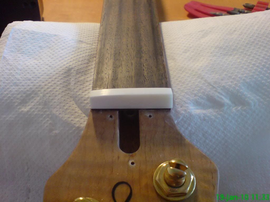
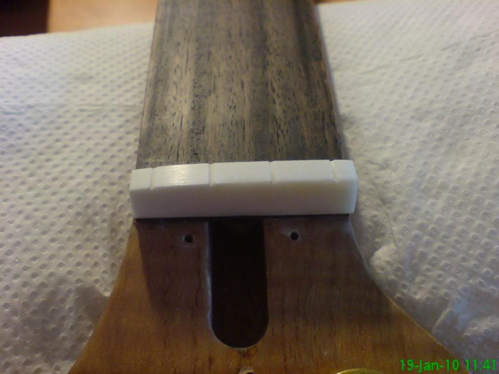
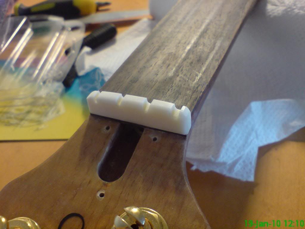
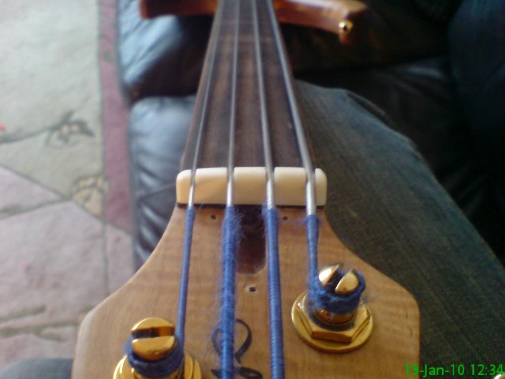
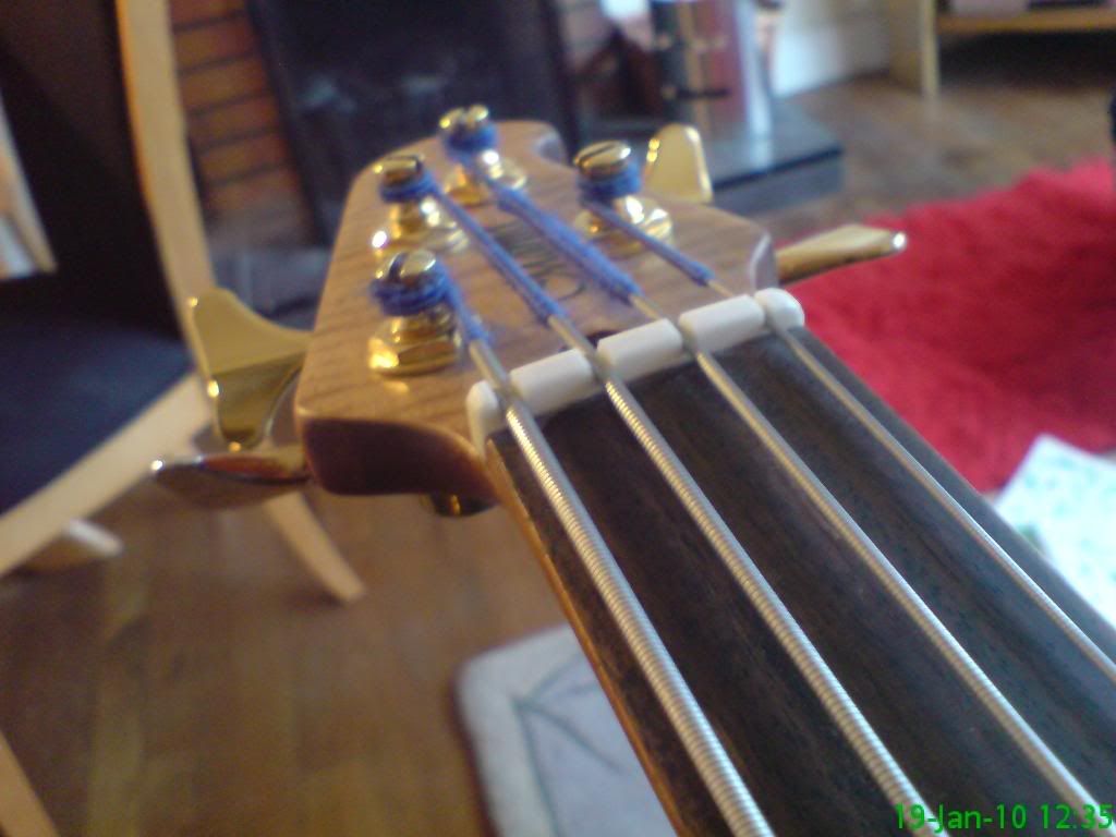
Made/retro-fitted a replacement nut (it is interesting... really)
Learned how to lie more convincingly - see above!
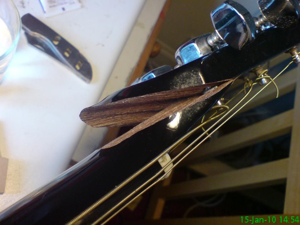
Repaired a broken neck

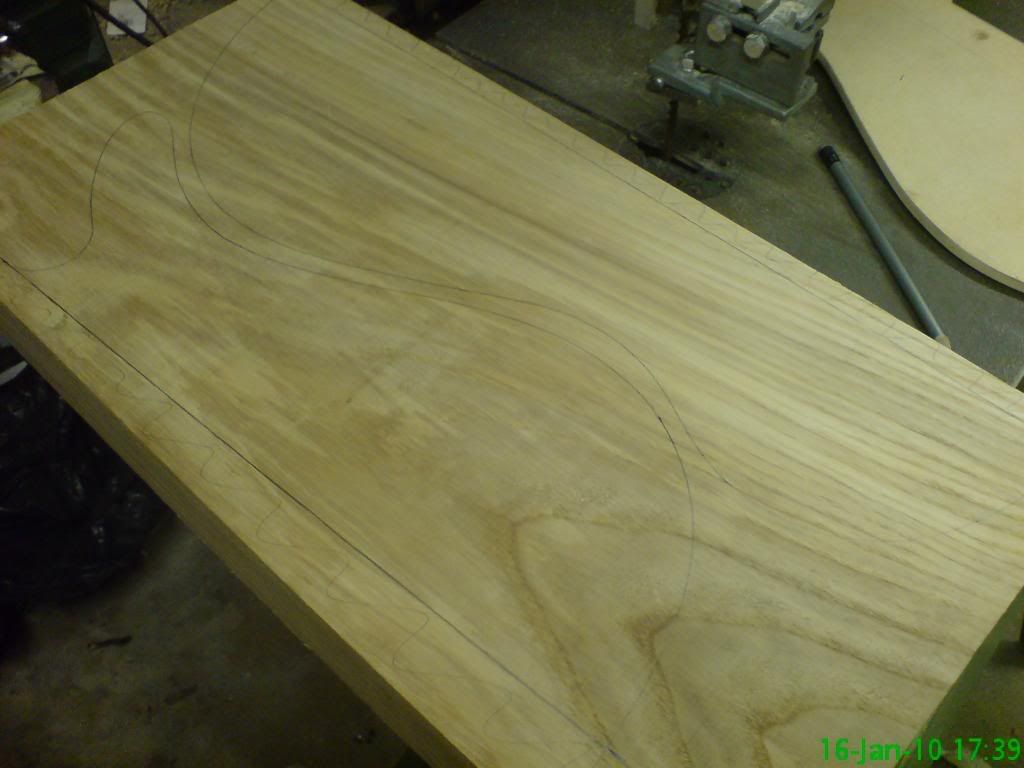
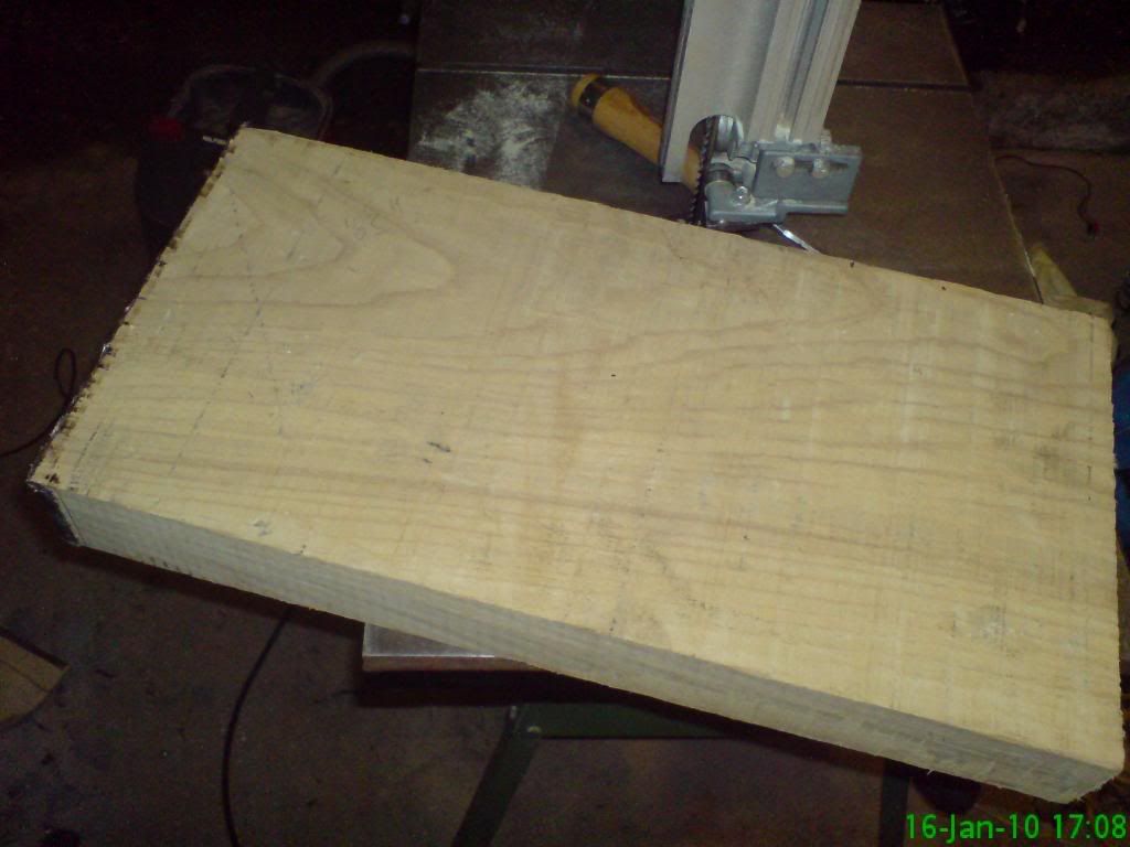
I found a piece of Ash from a build I did in 05/06 - it was large enough to make the wings of my bass design from, so I decided to try the bandsaw out for what it was intended. Bear in mind that Ash is pretty hard, it is the reason my old cheapo Ryobi bandsaw is hosed - just couldn't manage it.

2 1/4" Ash, semi flamed on inspection! Beautiful!

Photobucket

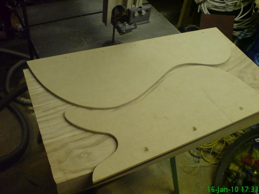
My design:

Photobucket

My templates have an extra inch or so on the edge to allow me to attach them to an over-sized blank for the sake of stability when routing to finish the edges. This is why it doesn't' matter that they are over-hanging.

Photobucket

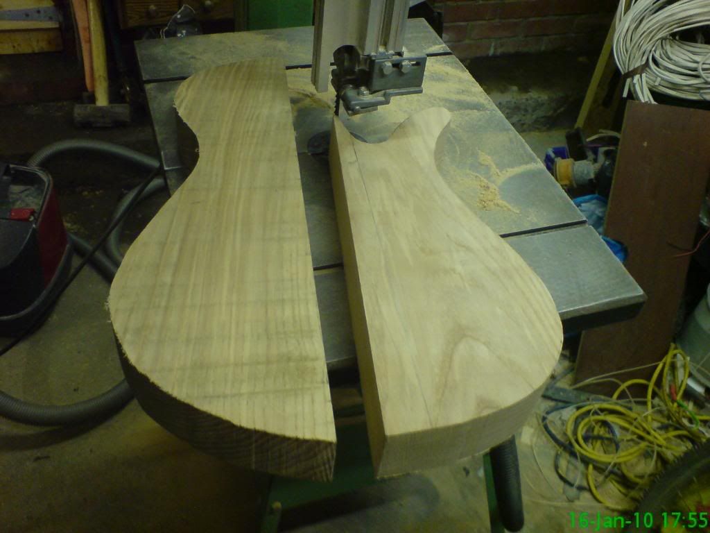
This is the final shape from the cutting. This was done about an hour faster than normal - minimum! I remember cutting that Ash the last time - it was a nightmare!!

Photobucket


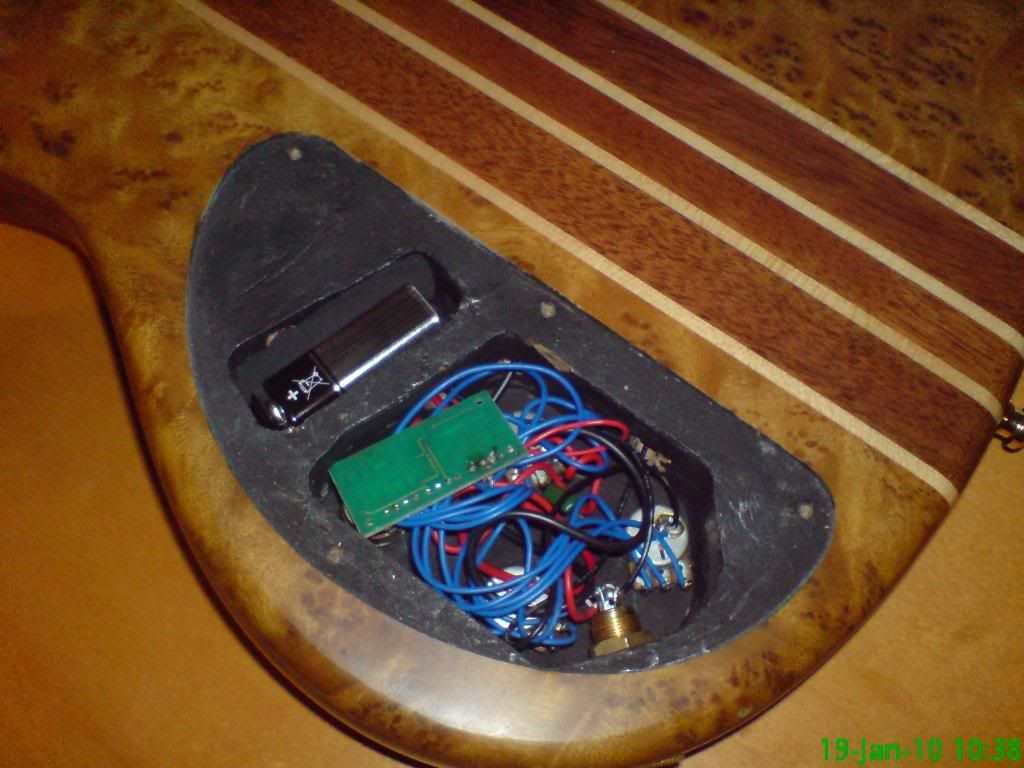
I got a rather fancy looking bass in to repair. To the naked eye it was made with a burl wood and lots of exotic materials, but it sounded TERRIBLE. I refused to believe that woods which would have cost £300 for the build were going to sound soo bad, so I reckoned that they had somehow put an image on some plastic wood (not an oxymoron... Ibanez use this), or used MDF or something. It still baffled me, but the grain was all wrong. Anyway, I HAD to know. I opened the back plate and found this:

Photobucket

CONFIRMED! Injection moulded chipboard! I am amazed at how real they make this look. I bet 95% of people are fooled. I am disgusted! Anyway, I wasn't paid for my opinion, but to replace the nut... more rant.

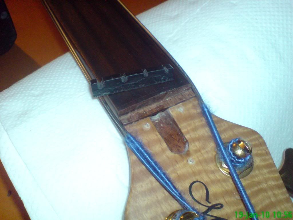
The nut was in to be replaced because it was wearing out (plastic nuts are horrid, weak and have NO tone - but then I am just a little biased). So I took the nut off - gentle tap with a hammer:

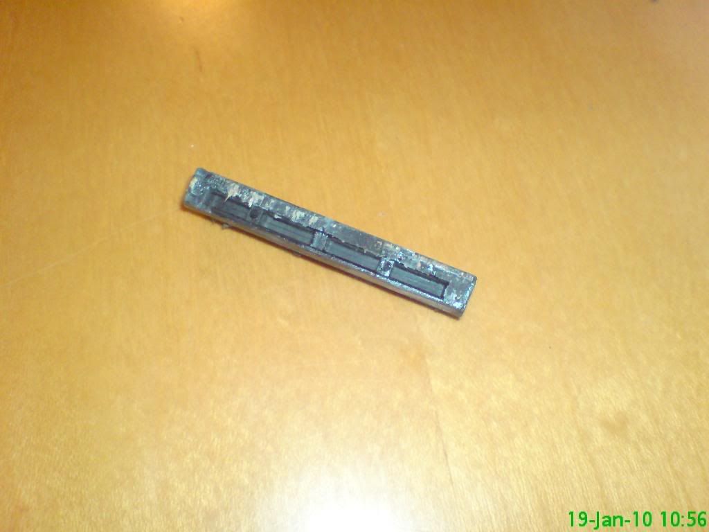
Photobucket

Cheap ROT!!! Injection moulded plastic, and not even solid!! People, if you have a plastic nut - do yourselves a favour and replace them, the benefits are seriously worth it!

Photobucket

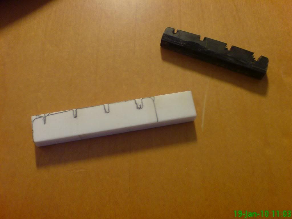
This is the replacement blank - rough sketches to show you how it will look - these are not my measurements... just rough! The nut I am using is bone which is legally sourced (ie not Ivory), and it weighs a lot - for it's size. 10x the weight of the plastic nut I reckon. It works nicely and smells HORRIBLE!!!

Photobucket

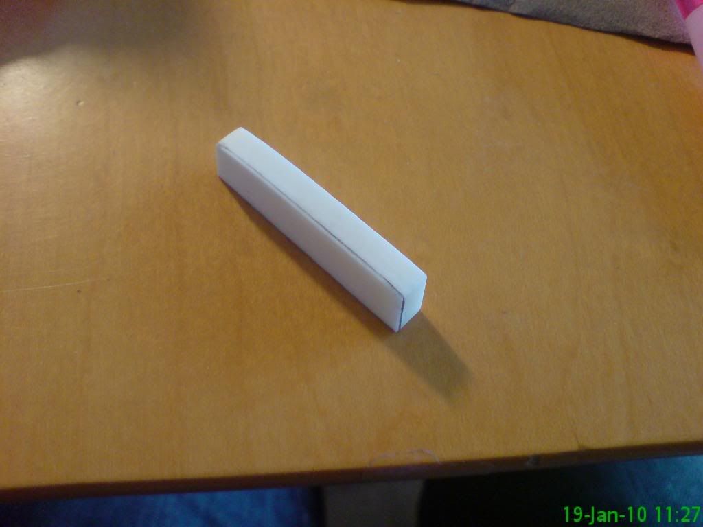
Getting the depth and width right:

Photobucket

Sitting well, despite the slot that was there being over 90*, so I had to file this to about 93* or so. No big deal.

Photobucket

These are my light initial marks for guidance:

Photobucket

This an initial slotting and shaping pic:

Photobucket

Finished!

Photobucket

Photobucket


Operator's note - this is NOT how a headstock joint should look:

Photobucket

It is now fixed - no pic of that though, will probably get one soon!

That will do me for now - currently clearing the workshop. What a task. I don't have the motivation... more coffee?

Best wishes :)
Mike
Tuesday 19 January 2010

Bandsaw

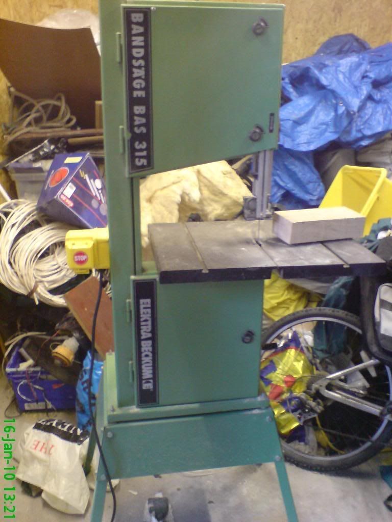
I was fortunate to have a friend whose father was a retired carpenter and happened to have a saw which totally suited my needs - a good tool as well! I picked it up last week and here are some of the things I have been working on before putting her to use.

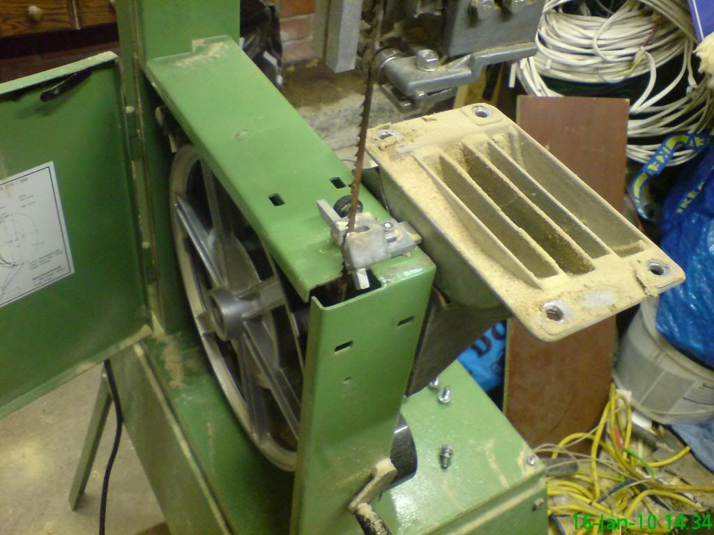
This is how it looks (if these photos look odd it is because I rotated them online).

Photobucket

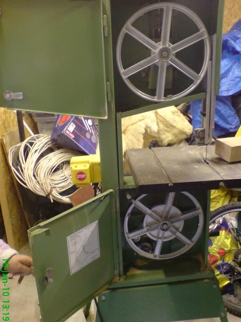
And the reason it is called a bandsaw - the blade is a band of toothed steel which runs around 2 pulleys, 1 of which is driven - in this case by a 550w induction motor.

Photobucket

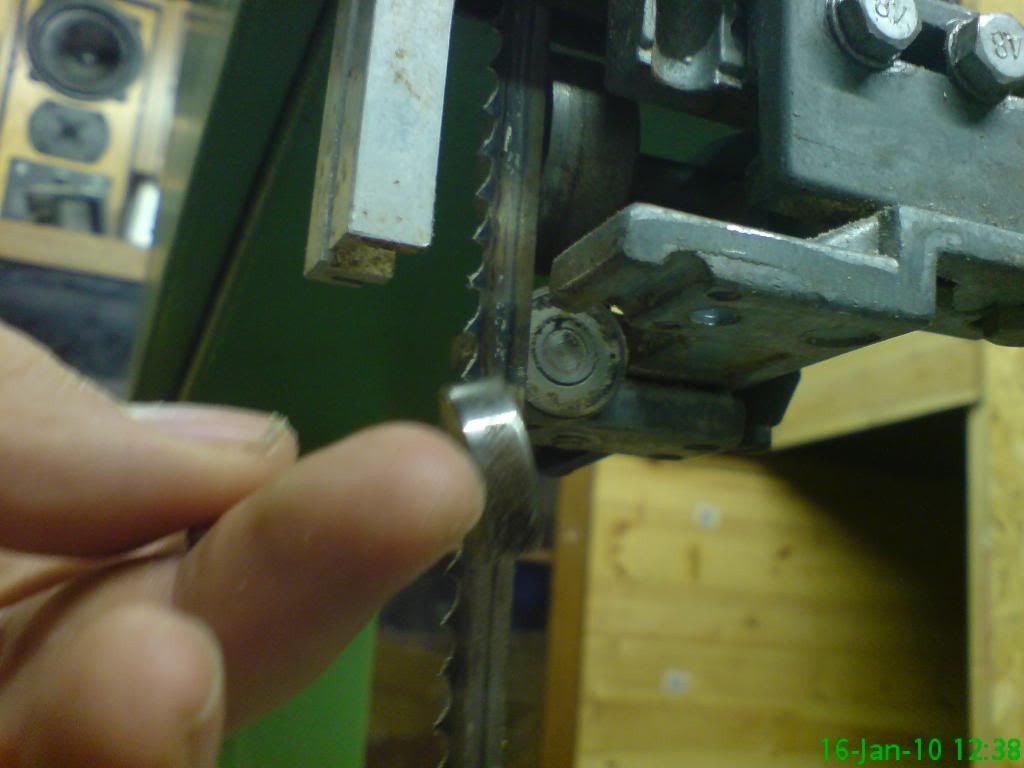
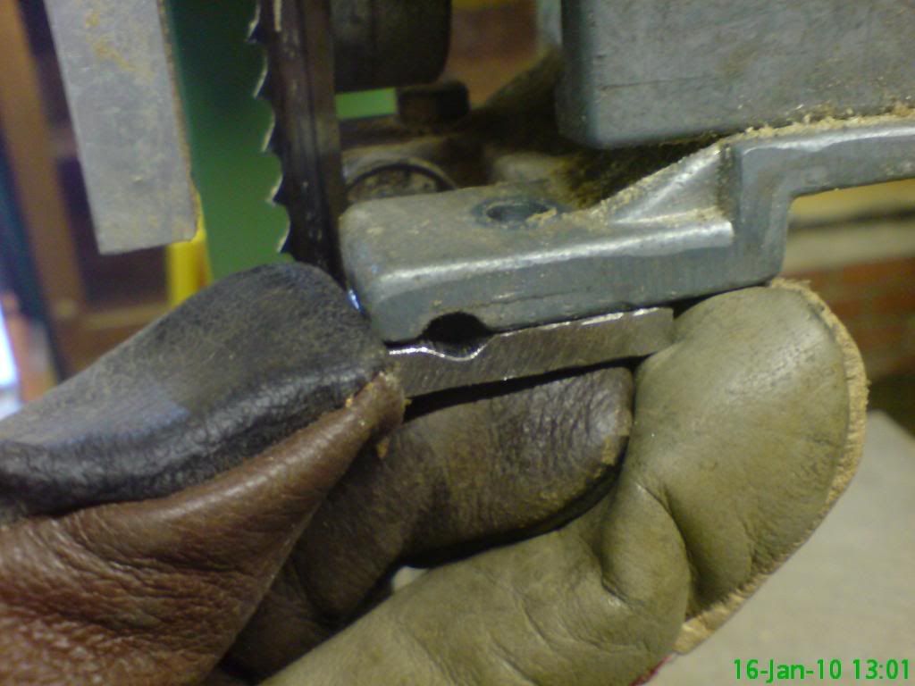
One of the top guide wheels was supported by a fractured piece of cast aluminium (rubbish material really) so I set about replacing that. Firstly the wheel, and a look under the top guide mechanism. The left wheel support is fine.

Photobucket

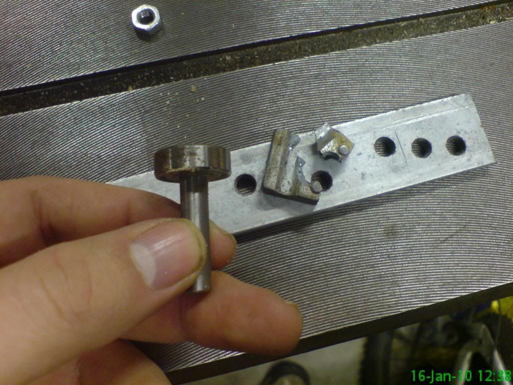
Here you can see the fractured holder, and the 1/4" metal strapping which I planned to cut to suit. The hole in the strapping both suited the bolt position and size! Nice, eh!?

Photobucket

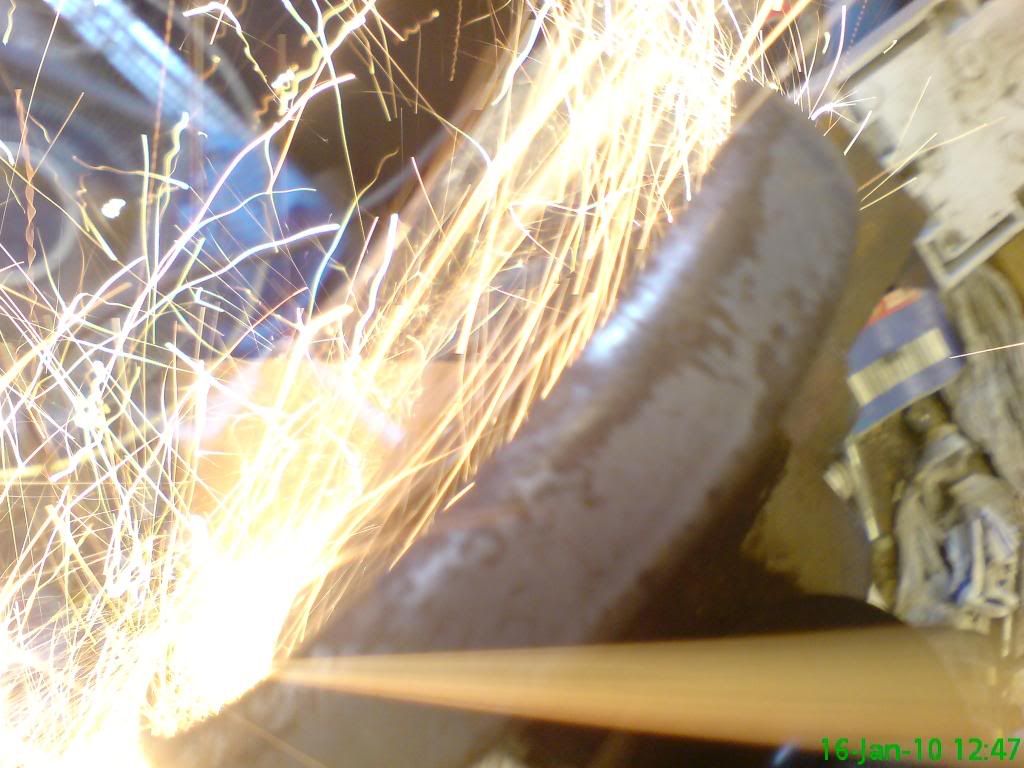
I really just break things so that I can angle grind stuff... or take pictures of me angle grinding stuff... honestly! (not really)

Photobucket

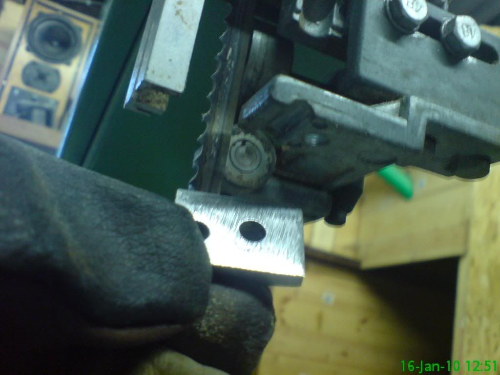
This is the replacement shoe which needs a slot ground in it.

Photobucket

There is the shoe with the slot ground - far from perfect, but close to "good enough"!

Photobucket

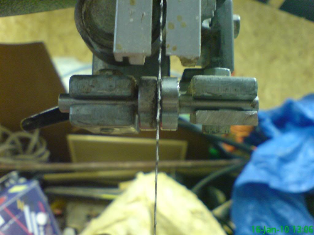
Here is the top support set correctly - all guides are not touching until pressure is applied in that direction.

Photobucket

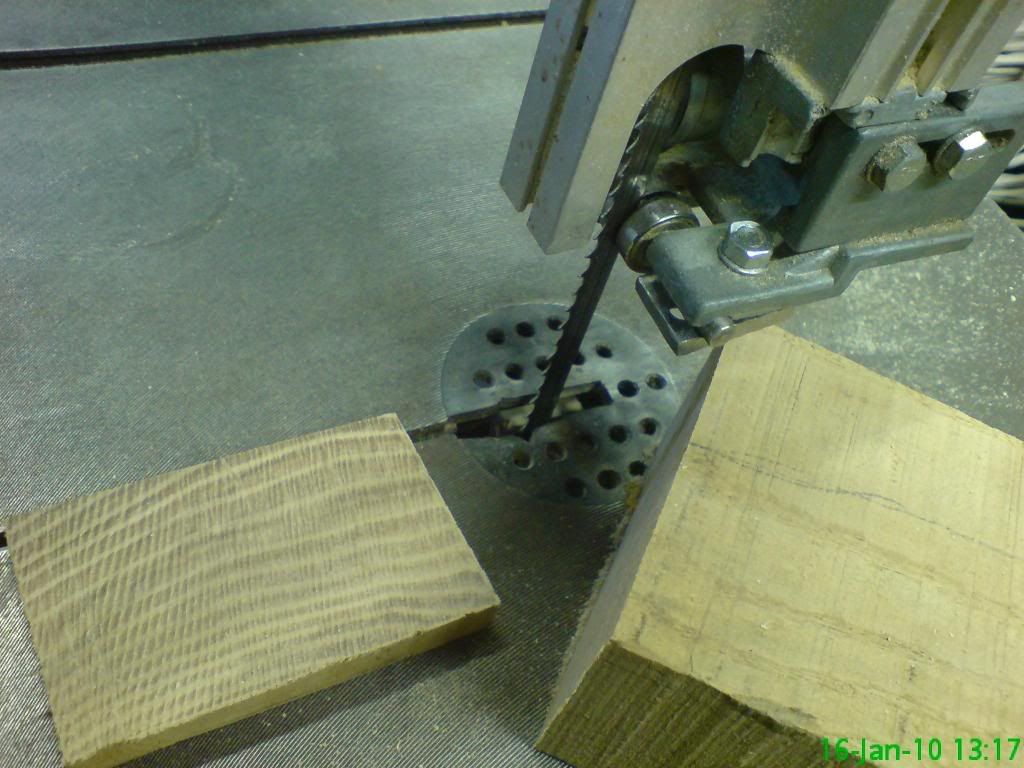
And a cut from a piece of 2 1/4" Ash - all working well!

Photobucket

The owner before Ronnie had this set very poorly. (Ronnie used this saw once or twice, but never had the call to, so all comments apply to its previous owner) Out of interest I checked the bottom supports, and the right hand ceramic pressure support thingy (technical term) was deflecting the blade by almost 1mm - BAD. The rear support wheel was about 10mm from the blade!! BAD. All set properly now!

Photobucket

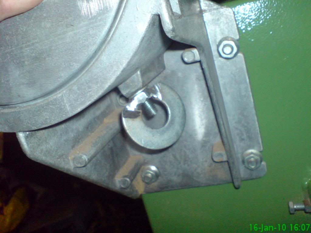
To get to those fixtures I had to remove the cast iron work top and the bolt that secured it was cast into a plastic wing-nut which had rounded and didn't grip any more. I broke that away, removed the bolt with spanners. I then cut a large washer and had my dad weld it to a suitable nut. I cleaned it up with an angle grinder (woo) and it works better than ever! (considering it never worked...)

Photobucket

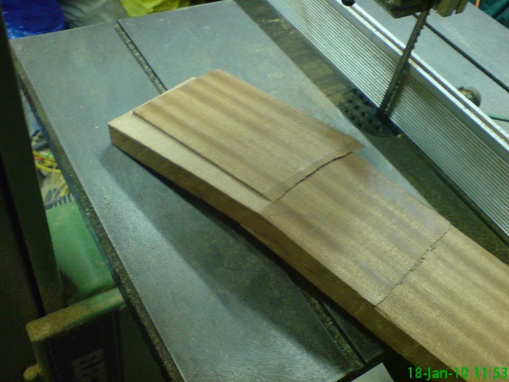
I will do the same thing for the guide stanchion on the front of the tool - same plastic rubbish nut. I put a wing-nut on there, but it is too small for my delicate fingers to work with! Here is an example of a rip-cut from a future guitar neck:

Photobucket

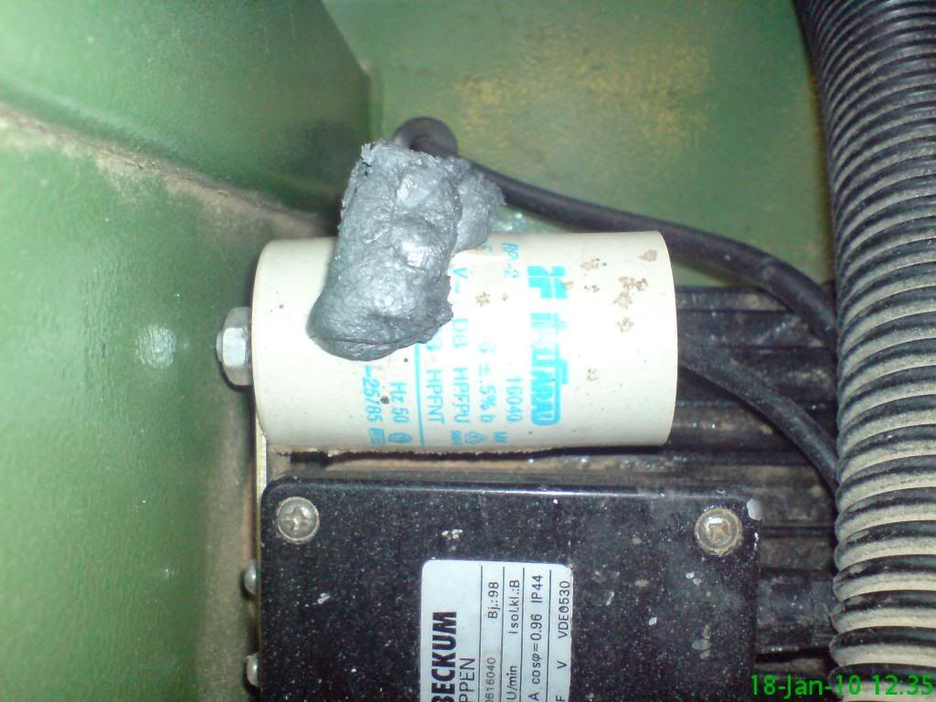
MUCH to my surprise the starting capacitor blew while I was lightly using the saw!! Now load on the motor wouldn't cause this, and there wasn't even much of that, so I guess it was defective, it is 12 years old after all. Still, I didn't want to see this:

Photobucket

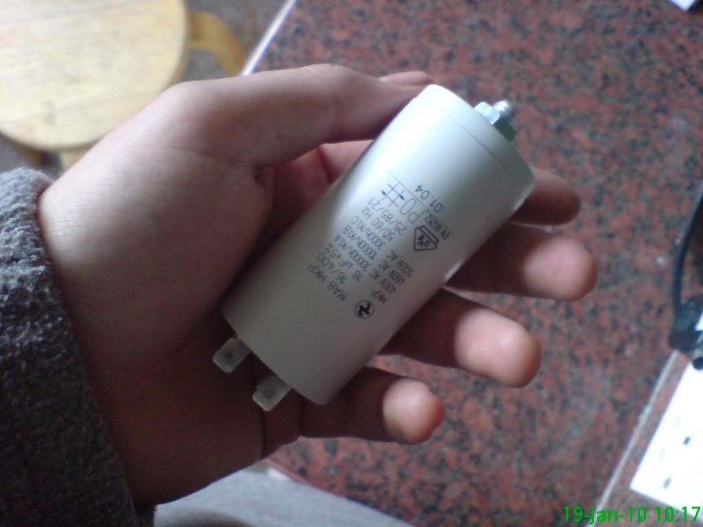
And for the grand price of £5.95 inc. postage I have a replacement part! For anyone running the Elektra Beckum or Metabo BAS315 (and 316/317 - the updates) the start capacitor for the 0.55kW motor is labelled "16400". It is 16 micro-farads @ 400V.

Photobucket

I have some good examples of scroll work to post up, but this post is long enough. I will sign off with a few points.

5/8" (15mm) blades for rip sawing large depths coming - 6 and 3TPI versions.
1/4" (6mm) blade @ 10TPI for general finer sawing on the way.
I found some suitable hardwoods locally. When I manage that bank job I will drop a bit of cash and start building more instruments.
I have 2 bass body wings cut and ready, and 1 guitar body wings cut and ready.
There will be an 8 string guitar this year.

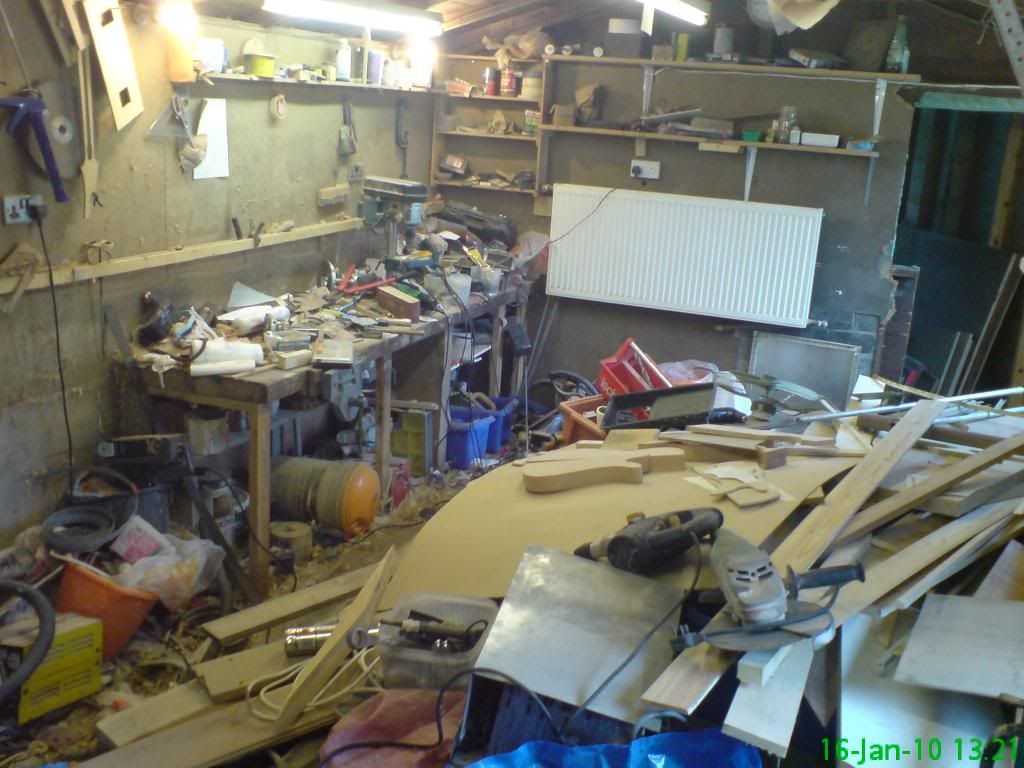
Finally, since no-one would believe this unless they saw it - this is half of the workshop... and tomorrow I start tidying.

Photobucket

Good night and God bless,
Mike

Thursday 14 January 2010

Computer Build #5

Right, this will be the final instalment until one of 2 things happen:

1) I decide not to get water cooling (in a month or 2) and make the outside pretty.
2) I decide to get water cooling and replace the drive bay covers.

If I decide to pretty it up now and get water cooling, I will not need that big fan at the front - or I *may* not need it, so I would quite like the case to go back the way it was, looking all normal at the front. Though I might decide to keep that fan. Actually I probably will, but I don't want to make a rash decision, so there is no rush to pretty this up, so I can leave it as it is until I make a final decision.

The advantage of the water cooling - 4.5GHz. Need I say more?

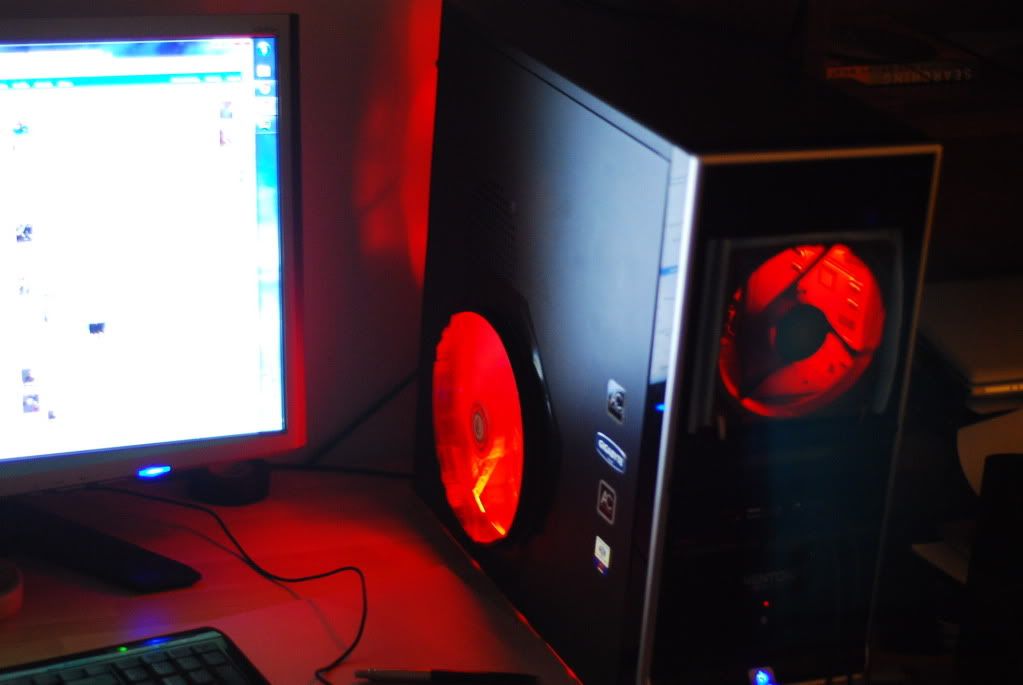
The purpose of this post is to show off the lighting. I couldn't resist putting a cold cathode lighting setup in this - I figure that if the chip catches fire, I may as well have the case glowing red so that I don't notice at first thus lessening the blow of my i5 processor going down the toilet, hahaha! I am usually not one for "speed stripes" or "things" but I just wanted to do this, after all I did build this with an angle grinder, so here goes.

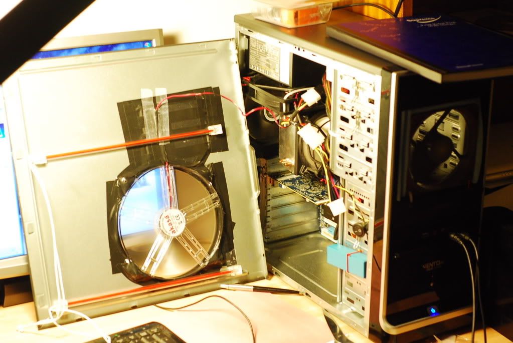
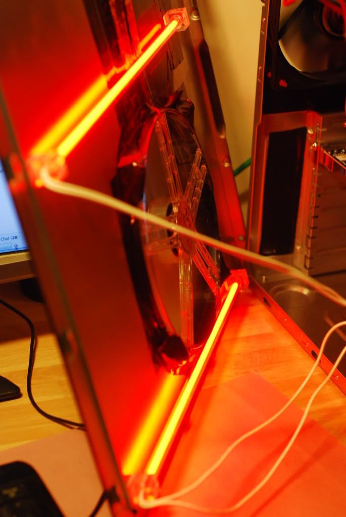
2 RED CCTs, mounted to the side panel - the tubes cannot easily be seen here, so aesthetically this is the best choice.

Photobucket

This is how they look when running:

Photobucket

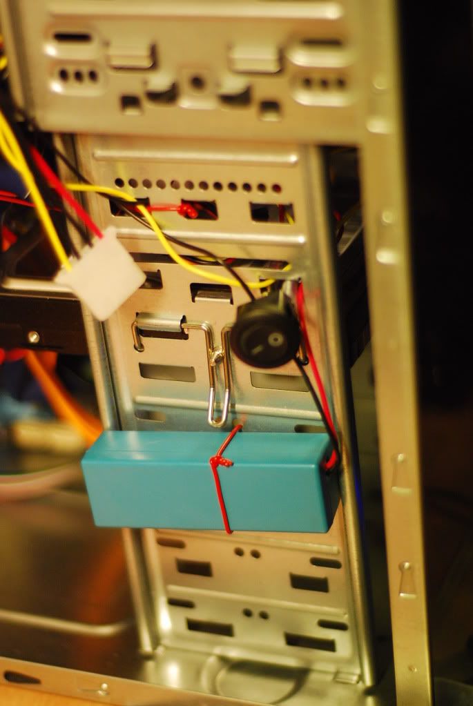
This is the wee transformer. Note the black switch (out of focus due to wide aperture for light) - it is huge. Where exactly did they think it would fit? Was I going to drill a 12 or 13mm moutnting hole in my case? Seriously guys, thanks for supplying it as a quick fit, pre-wired job, but that switch is a real huge ugly brute.

Photobucket

All set and whistlin' dixie!

Photobucket

Here is a picture showing a little... unconventional wiring. Well it is conventional in the sense that + to + and - to -, fingers in the mains socket standing in a pool of water barefoot next to a lightning conductor on a stormy day, but since I ran out of fan jumpers, I pushed single core wire into the back of one of those 3 pin plugs to create the connection. People are too precious about the power drain through these. News flash: the fans are about 2 watts each... I'm not loosing sleep. I know, I know - I can't control the fan speed by jury-rigging them, but my motherboard only supports speed control on the CPU fan and *maybe* 1 peripheral fan. I have speed control disabled - I want these working hard :D

Photobucket

That is all for now, computer wise. Here are some things that I plan to do in the next month:

Collect a bandsaw (all being well, tomorrow! Amazing to have found one, what a God-send)

Chamber ensemble and Indian (Haydn, Handel and Bhuna... Friday night sorted!)

Design some more instruments

Continue preparations for "Sweeney Todd" which will be performed in the Mill Side Theatre as the NI Première (Theatre at the Mill). This is running from 2/2/10 to 13/2/10. Again, on my birthday I will be playing trumpet, and I wouldn't change that for the world :)

Write more music - I plan to write maybe a head-chart a week and post it to my blogger as inspiration, I might start with one I have already written to give me some buffer time!

I will have to clear a workspace in the workshop. I have been preparing for this day... I am still delaying! Man alive. Could it be more messy? The answer is no, and I will post a picture soon, no-one will expect the level of mess. Only people who have seen it will believe it.

Keep to a better sleeping routine: 8-9am bedtimes and 1-3pm getting-ups is horrible, I feel like such a waster when I do this and I hate waking in the dark evening! Last night I managed a 12am bed, sleep by 2am, up with no alarm clock at 9.30am. More like it!

That is all for now, I won't continue an endlessly boring list for no reason, besides there are things which I don't want to be accountable for, like clearing the back drain - but I did that already. Horrible day that was!

Here's hoping! (hopping)
Mike
Sunday 10 January 2010

Computer Build #4

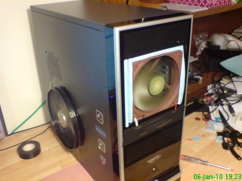
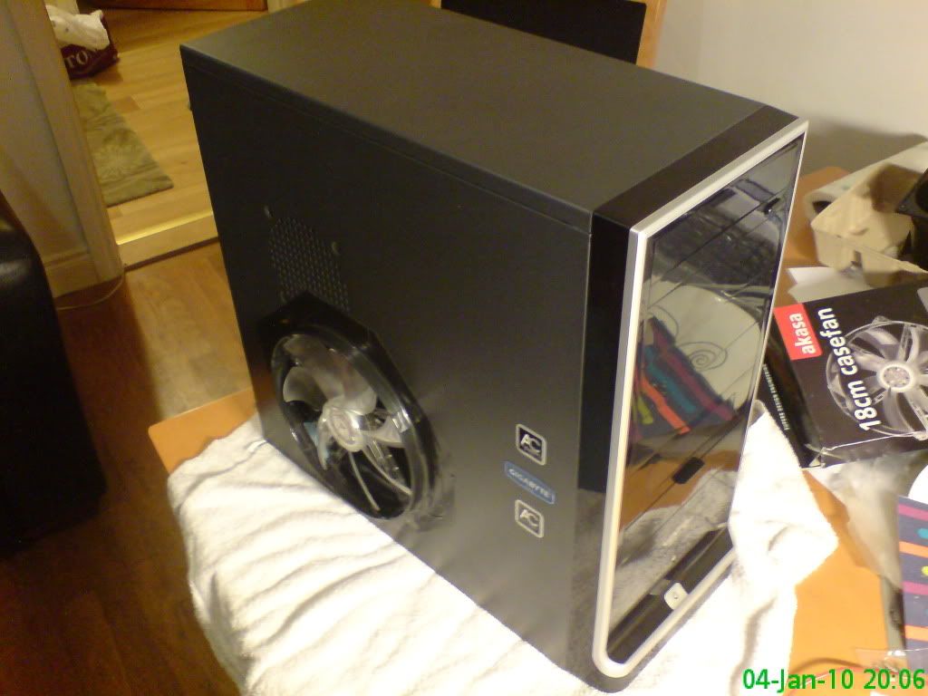
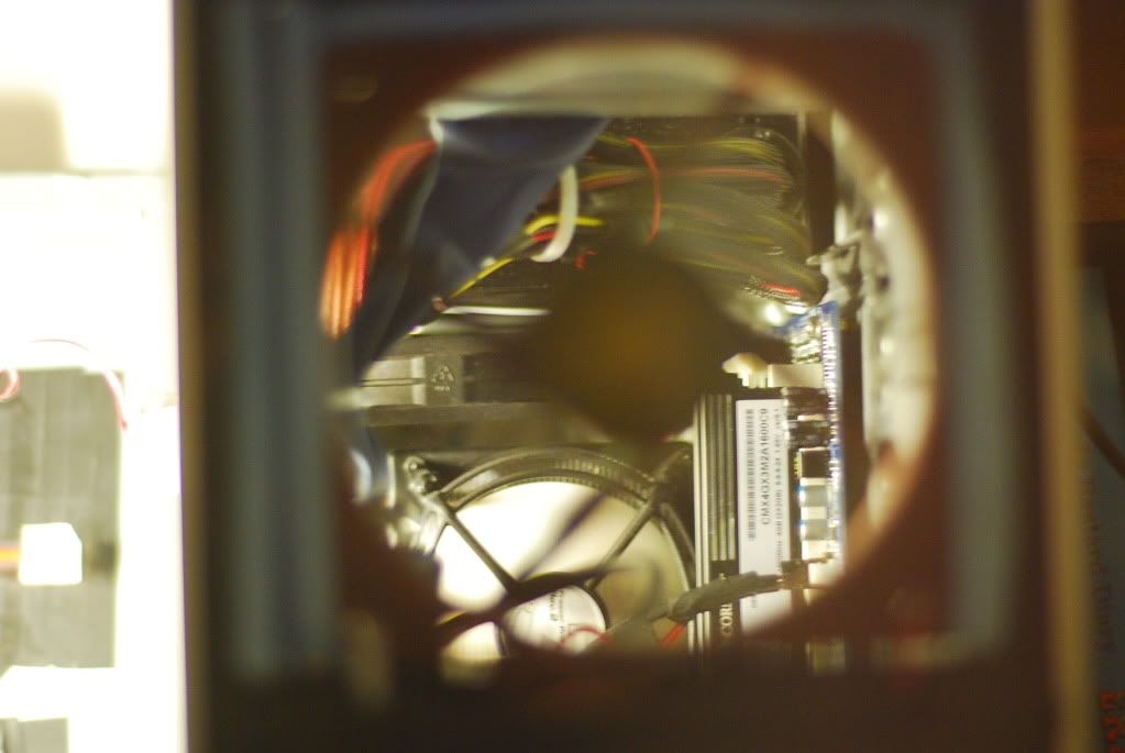
This is an update concerning the cooling solution on my computer. By messing with the order of fans and the case layout a little I have managed to drop the overall temps by 6-10*C. The main reason for this is airflow, or the lack thereof. The intake vent on the front panel of the case is abominable! It was providing no throughput, so I decided to take out the 5.25" bay windows, cut the spacers away and install a fan there.

Now I did every iteration of fan layout possible, measured my temp tests under all the circumstances and what I now have is probably the best I will get short of replacing all the 120mm fans with that Akasa Apache which kicks out 60CFM. Also, the next logical step is water cooling, but I will only venture there if the summer's heat drives me to (haha, NI heat) or if I want to bump up to 4.4GHz.

Onwards. I am currently running the PC in a room which is getting warm (thanks fire) and I will be able to stress test as-if the summer was here, and actually warm. More on that later (at a cursory glance the temps have gone up a few degrees, but not much.

What I did:

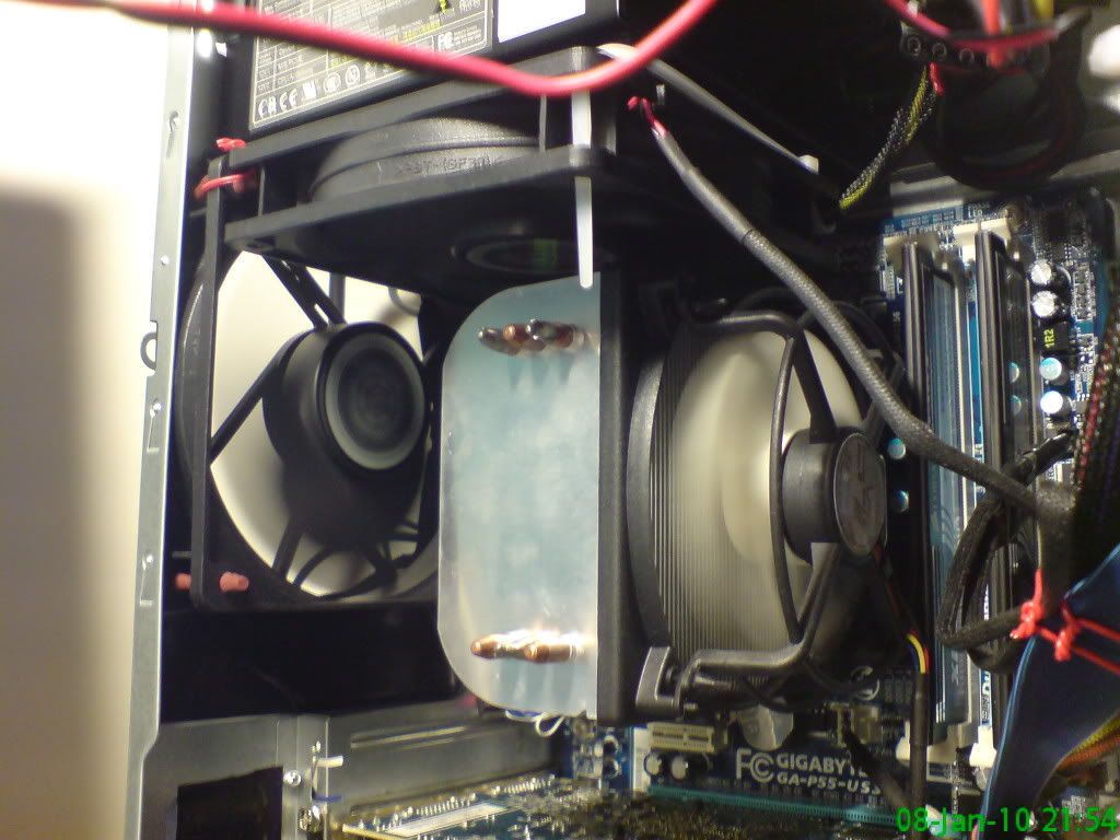
CPU cooler back to normal (ie 92mm fan).
5.25" drive bays opened, Akasa Apache 120mm fan installed sucking in.

Photobucket

Rear 120mm fan extracting.
120mm fan (perpendicular to the rear case fan, sucking air through the CPU cooler and out the PSU fan).

Photobucket

So in that burn test I have it from a peak of 82*C down to a peak of 74*C... much happier now!

In any case there is excellent air throughput now! Some temps for you (Idle):

Before (at new 4.1GHz clock):

Case: 21
CPU: 26
C0: 36
C1: 32
C2: 33
C3: 29
GPU: 35

After (also at 4.1GHz clock):

Case: 19
CPU: 20
C0: 30
C1: 26
C2: 27
C3: 21
GPU: 30

In the following test the 5 temperatures are the temperatures of the CPU die for each iteration of the test of which 5 were run.

Before (Improved Vcore, sub-optimal fan setup!)

Burn test (CPU temp):
53, 63, 66, 67, 67 with a core peak of 78

After (Improved Vcore and fan setup)

Burn test (CPU temp):
59, 62, 63, 63, 64 with a core peak of 74

Now some nerdy things. (turn away if numbers give you dizzyness!) Bear in mind that measured voltages don't often 100% match set BIOS voltages, so U try to give an account of both where applicable.

Vcore: 1.31v measured by CPUID (BIOS set @ 1.318750 I think)
Vin1: 1.62 - measured by CPUID (BIOS was set to 1.64)

Bclock: 216MHz
Multiplier: 19x
DRAM multiplier: 6x
Core Speed: 4104MHz
DRAM Speed: 1296MHz
DRAM Timings: 9, 9, 9, 24

All extraneous power BIOS power functions, power save, turbos etc etc... turned off.

My previous settings were something like (for the 4.1GHz clock):

Vcore: 1.36v measured by CPUID (BIOS set @ 1.3618 I think)
Vin1: 1.62 - measured by CPUID (BIOS was set to 1.62)

So initially I got the Vcore as low as possible by lowering by a step, testing, repeat. When it failed to boot and was unstable I bumped it up a setting or 2 and stress tested. Thermal implication is that lower voltage is obviously going to heat the chip less, and even though we are changing millivolts here, it really matters! I got ~2*C off the chip temp by getting the Vcore slimmed down! What I did find was that with the Vcore at its most efficient setting, I had to bump the Vin1 for the RAM from 1.62 to 1.64V. Note that the ram will work fine at 1.65V. (my Gigabyte m/board adds in .02 at a time, so 1.64/1.66/1.68 etc... but 1.64 is working well.

To break this down into manageable data:

CPU speed is a by product of the FSB x Bclock multiplier. Vcore supplies the voltage/power for the chip. This is nominally AUTO, but when clocking you want control of it.

On the i5 1.35-1.4v is about a high as they recommend pushing it.

RAM speed is a by product of FSB x DRAM multiplier. Vin1 supplies the voltage/power for the RAM chips. Again, this is AUTO, but in clocking you need the control to give the RAM more power when needs be.

You change the FSB to accommodate a higher clocking and since the CPU and DRAM are affected by this you may have to settle for a lower RAM speed.

It is recommended that the Vcore and Vin1 are kept within 0.5v of each other.

At 4.1GHz my CPU benchmark was 7115.5 which I am dead pleased about! I ran a bunch of stress tests. OCCT for 4 hours, Prime95 - 2 hours on large FFTs, 10 mins on small FFTs (I read that 10 mins should show whether the system would cope or not), hours on blend. Intel Burn Test - I ran the default 5 cycles, and it pushed the chip hard, but it was fine. I also ran SuperPi and LinX.

I am monitoring heat with:

SpeedFan
Core Temp
CPUID
Real Temp

Stress testing with:

OCCT
Intel Burn Test
Prime95
LinX
SuperPi

Benchmarking with Performance Test 7 on evaluation.

The settings which REALLY push the processor are the small-FFTs. I assume that stands for Fast Fourier Transform, and there endeth my knowledge on that matter! Also LinX gets her warm!

Now in the future I can see me running a water-cooled unit to get that 4.4GHz, but until then I may as well do some work on this instead of endlessly testing it. Currently a faster computer has led to less work done than ever (except computer faffing and searching for bandsaws...).

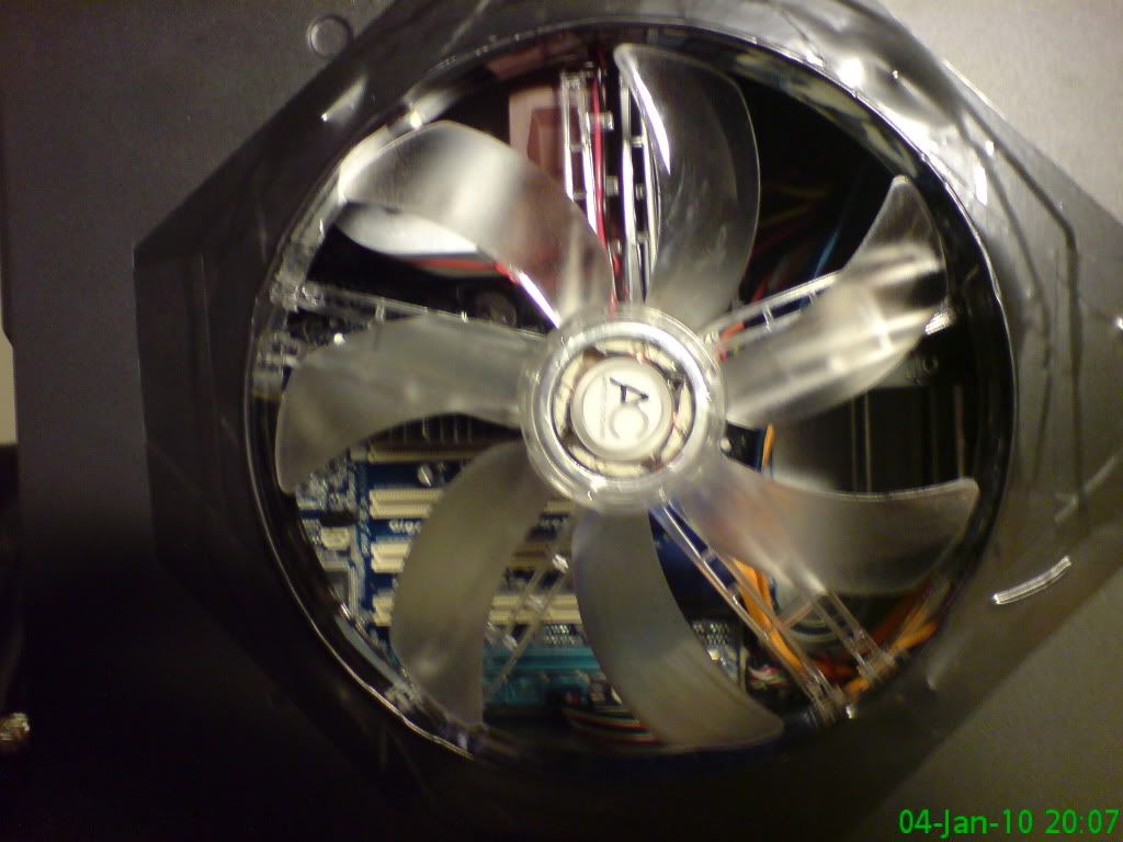
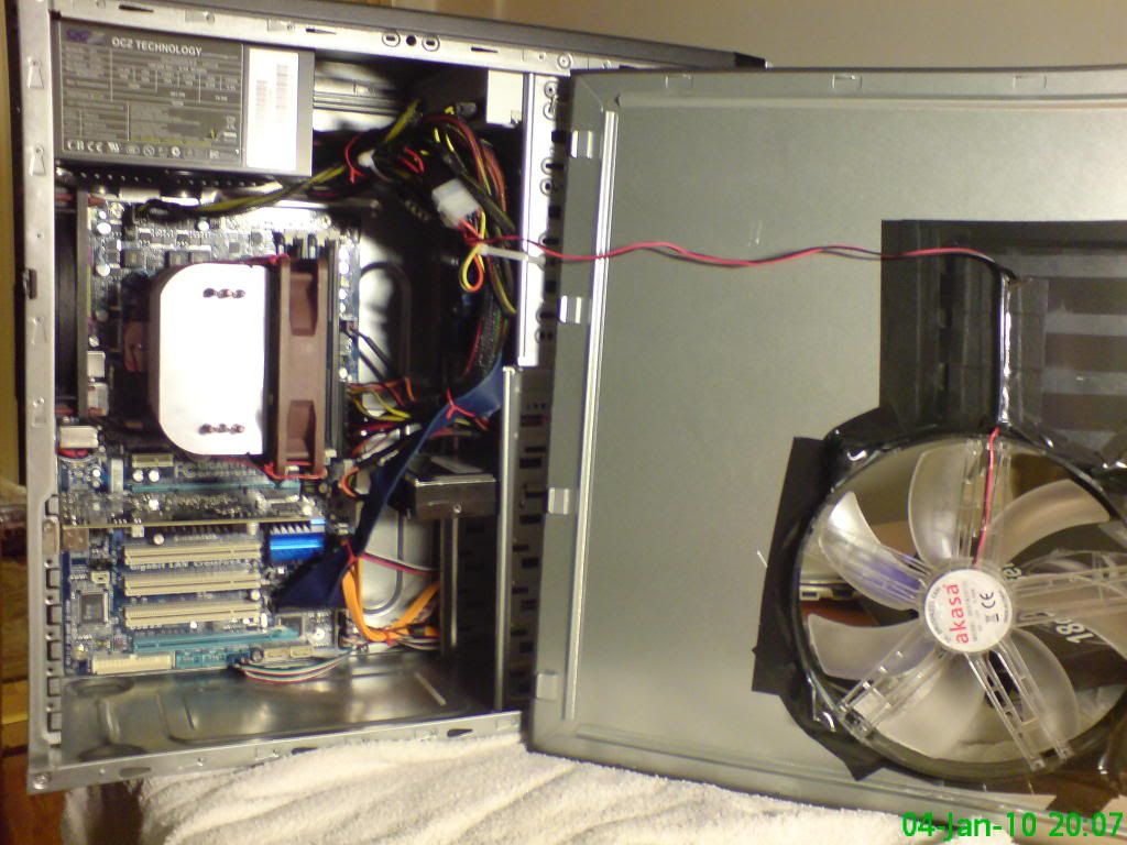
Finally, I have the black plastic 5.25" drive bay overs to cut up and make the front fans look much neater - everything is a bit "temporary" right now, and it will eventually look neat! That black tape on the side fan will be cut into a circle soon.

That ought to do it for now, I must process some photos and try to find a 14" bandsaw somewhere. I forget that we are in 2010... and I was born *after* imperial was the norm, so I should really be talking MMs more! 350mm would do :) I blame dad for my use of both systems (not totally illogical - lots of the guitar gear is american, and sometimes inches just work neater!).

God bless all,
Mike
Tuesday 5 January 2010

Computer Build #3

It is nice to be posting this from the new machine - it is really a lovely computer! And that was a spoiler. This may become 2 parts - I am getting tired. Lets get the good news out of the way first.

1) It works.
2) It works much better than expected.
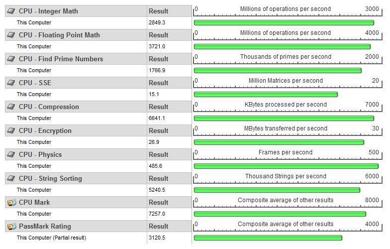
3) It achieved a CPU Benchmark of 7257 @ 4.2GHz and it seems stable (more testing).
4) There is more scope for speed, whether it is necessary or not.... ok, it is totally un-necessary, but the potential is there. I think 4.4GHz stable is possible.
5) Temperatures are all within reasonable limits, Idling quite cool.
6) Vcore settings not too high.
7) Not too loud.

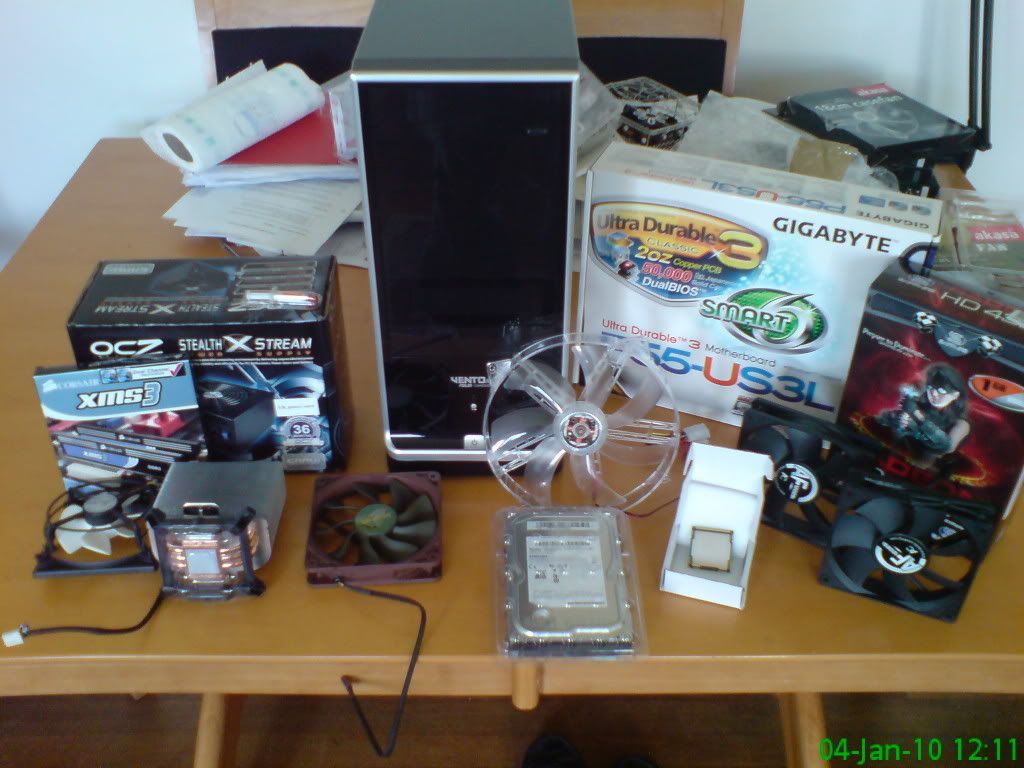
So I will get on with the talking. I got my parts this morning - having had a good 3 hours sleep I decided it wise to start building with angle grinders and what not.

Photobucket

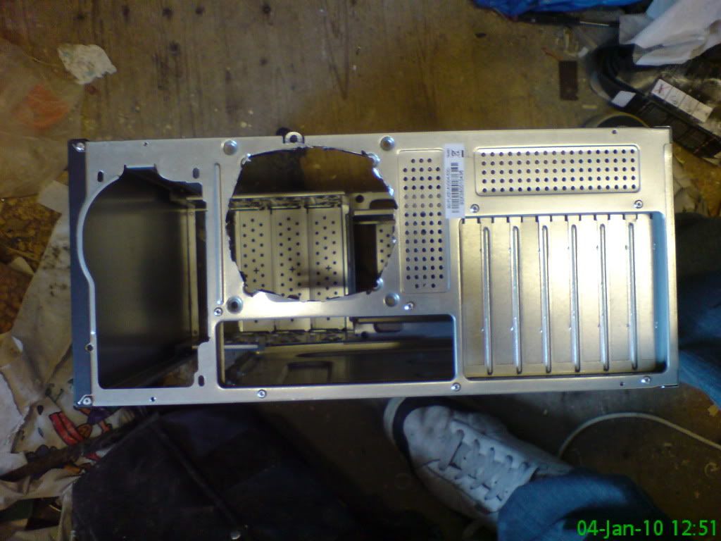
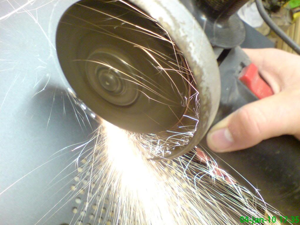
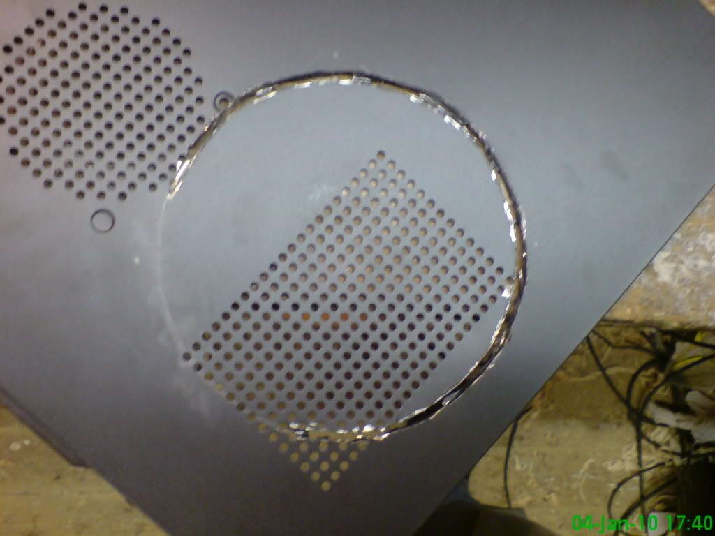
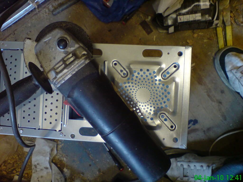
I started by cutting out the vent holes with an angle grinder - less impedance = more cooling. Bit rough, but good enough.

Photobucket

Photobucket

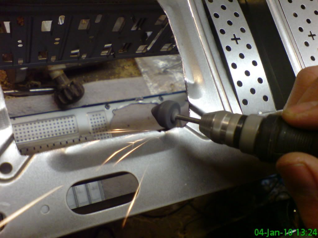
Smoothed off with a Minicraft drill + grinding tool.

Photobucket

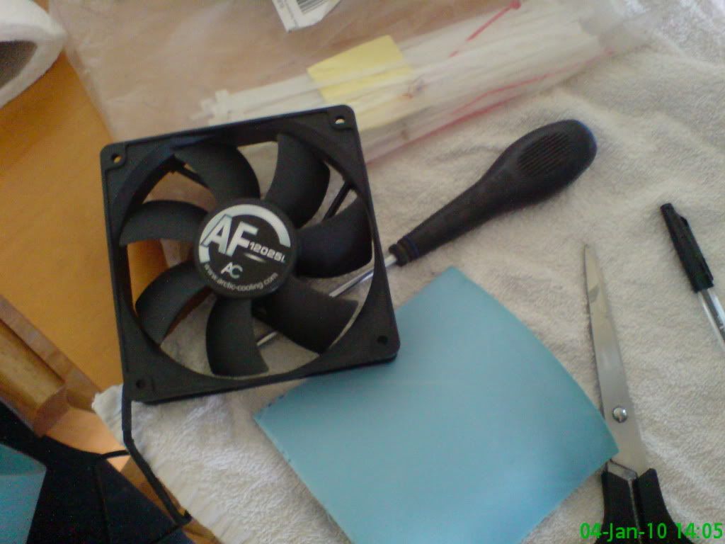
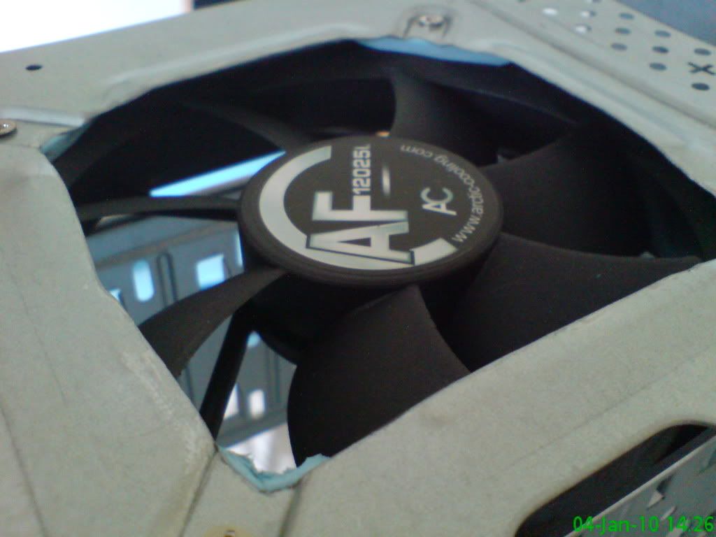
I then set about mounting the 2x 120mm fans with blue foam to stop them transferring too much vibration.

Photobucket

You can see how I used triangles to space the fan from the frame.

Photobucket

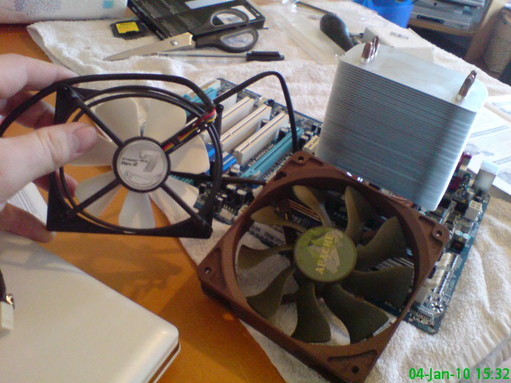
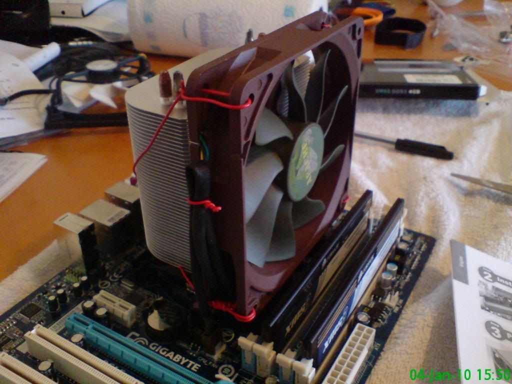
I then replaced the 92mm noisy CPU cooler fan with a quiet (18dB(A)) fan with a large 60CFM air flow (compared to 40).

Photobucket

It ended up looking quite neat!

Photobucket

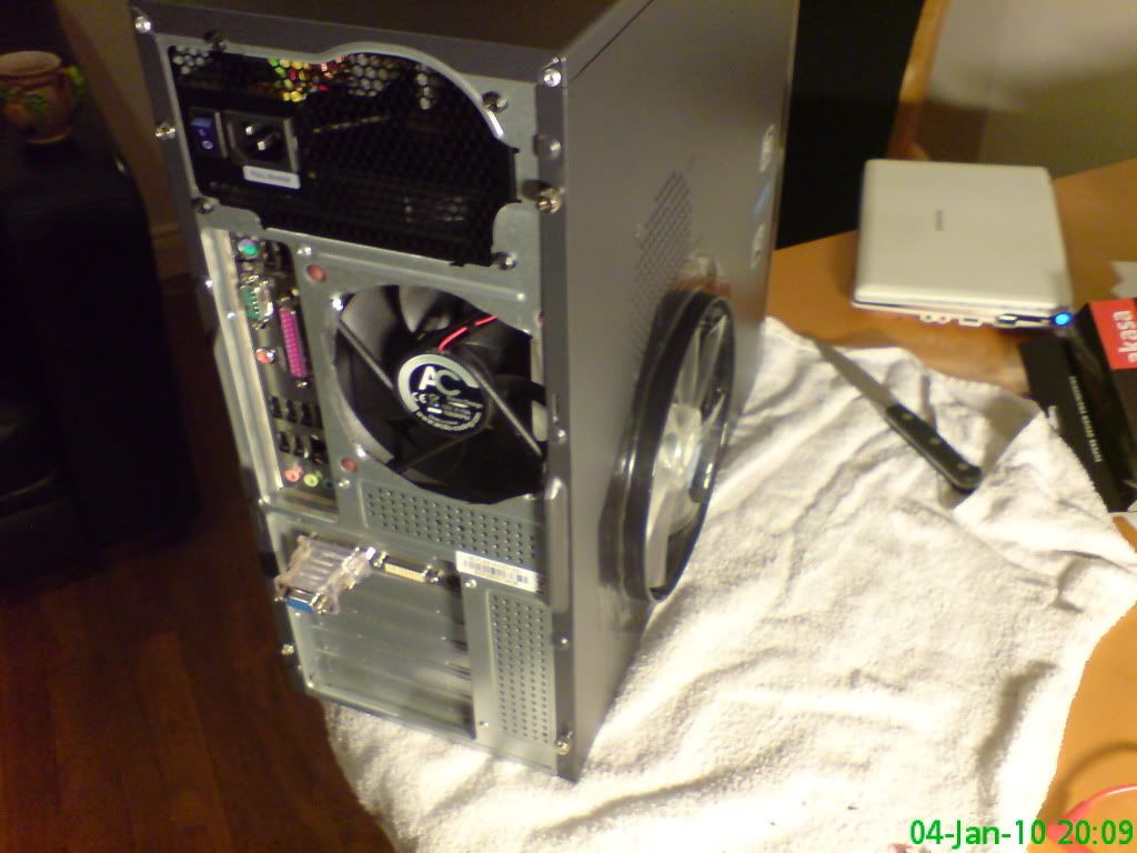
Now, cutting out the 18CM fan slot in the side of the case. Dangerous cutting and photographing at the same time... what's the worst that could happen (I just shuddered).

Photobucket

Quite circular for an angle grinder! (and for my primitive metal work skills)

Photobucket

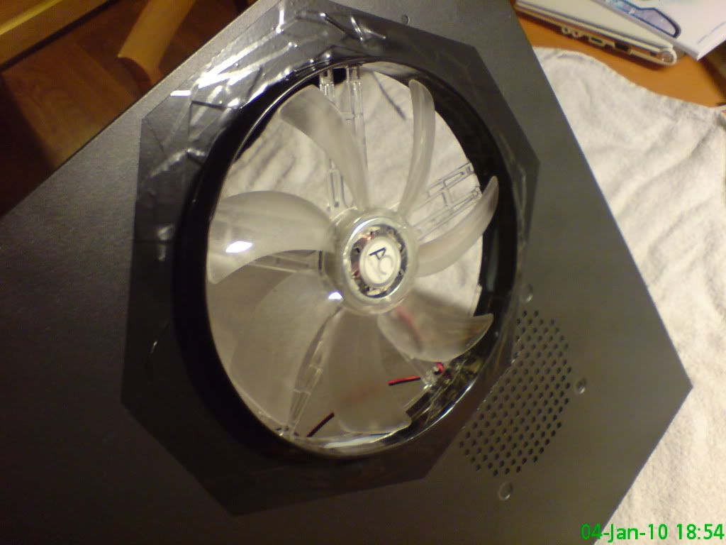
Sealed with tape, mounted with zip ties and spaced with the same blue foam. the tape is part aesthetic - the silvery edges from the cut looked a bit naff.

Photobucket

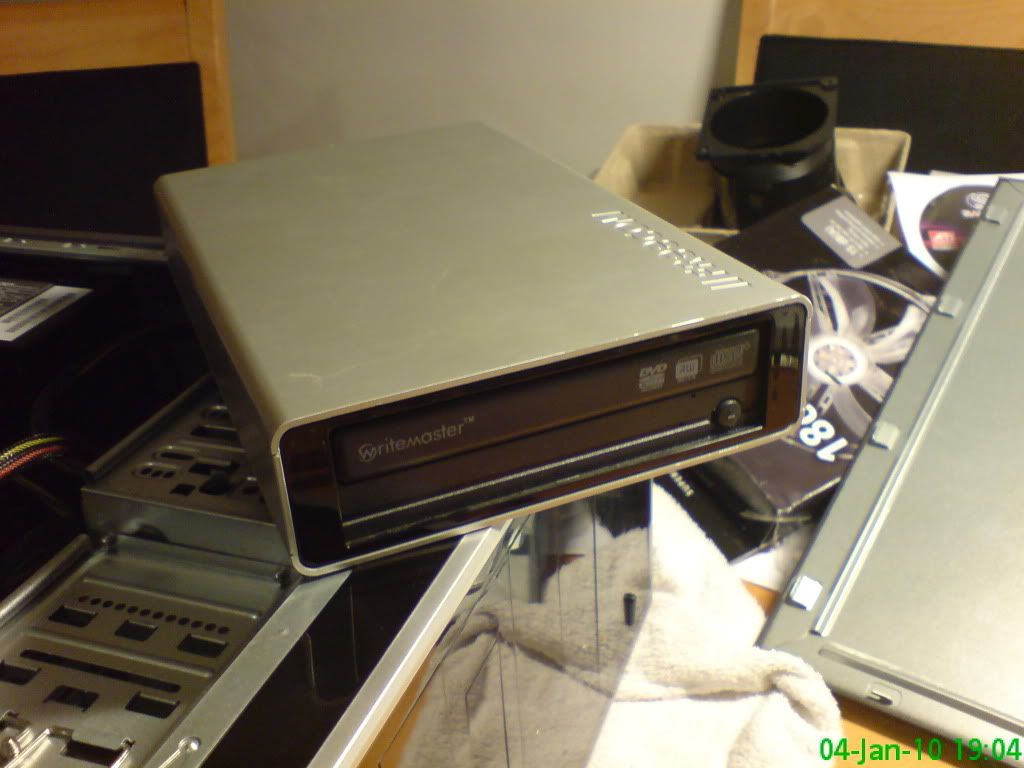
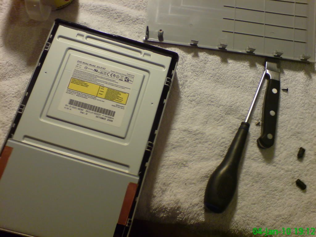
Now to cannibalise a DVD drive (external). IDE, but it will do until I buy (and can afford) an SATA drive.

Photobucket

There is the soft underbelly of the DVD drive!

Photobucket

Looking good!

Photobucket

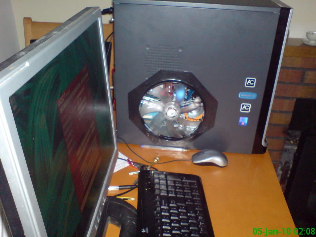
Big fan!

Photobucket

The black tape above the fan is actually holding on a piece of plastic which blocks an un-necessary vent. I blocked all vents off that did not have a fan in them - I want to control the air as much as possible!

Photobucket

Is this pretty... it seems it... in the same way a big V-twin Harley is...

Photobucket

Loading... it worked!

Photobucket

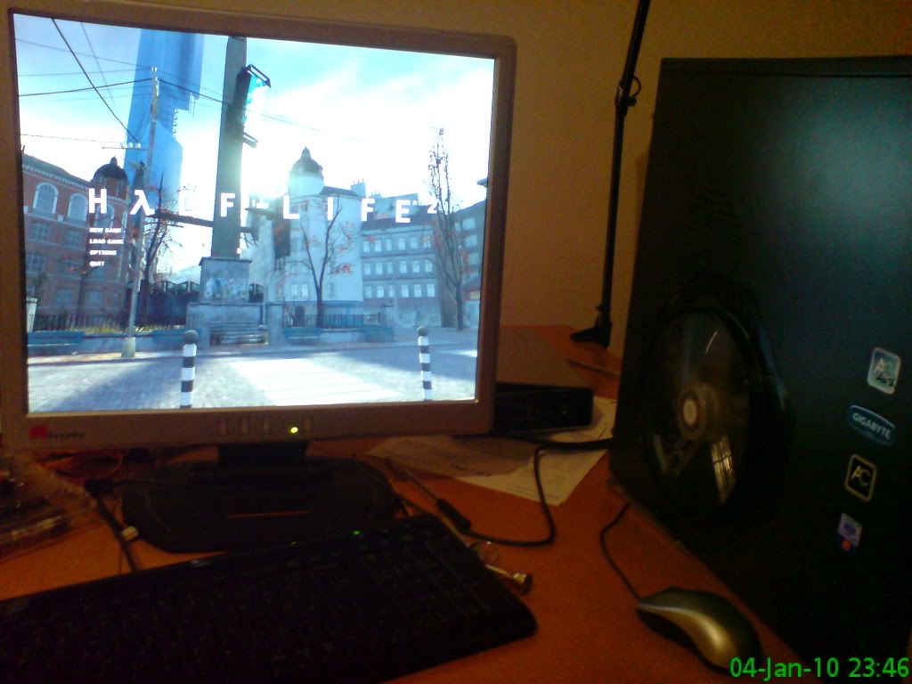
Testing with Half Life 2 - I am not a gamer, but I do own this game, so I may as well test it. 40FPs on the heavy stuff, 200-300FPS on the light stuff. Again, old game, not like Crysis! Also, this is my brother's monitor - just doing the build/test initially up home where the tools are! I have the benefit of a 22" monitor in my room, so that is nice for photos etc etc...
Photobucket

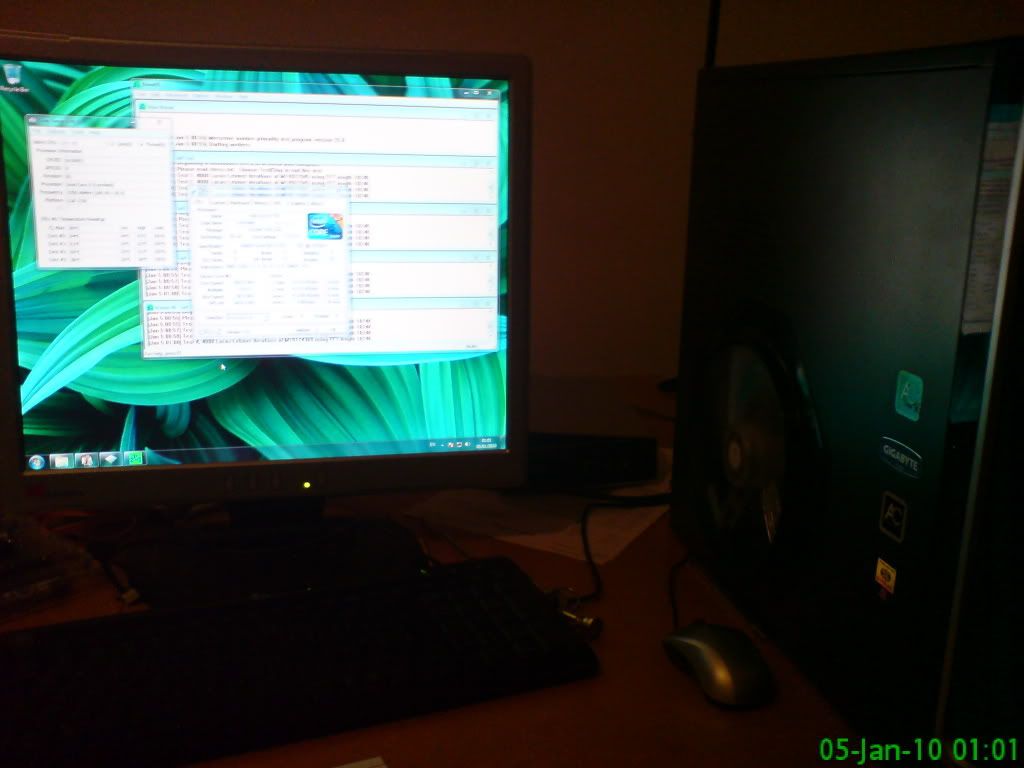
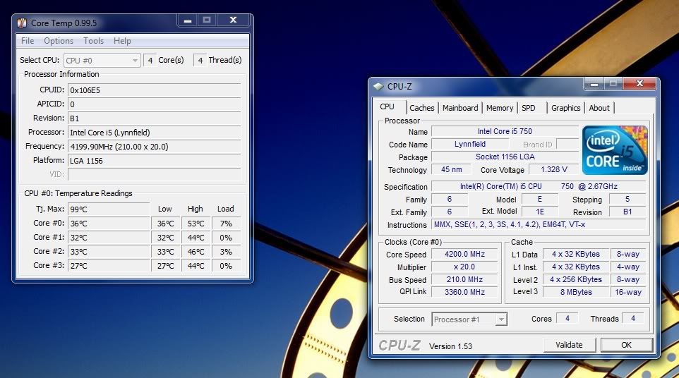
Checking out some over-clock temperatures.

Photobucket

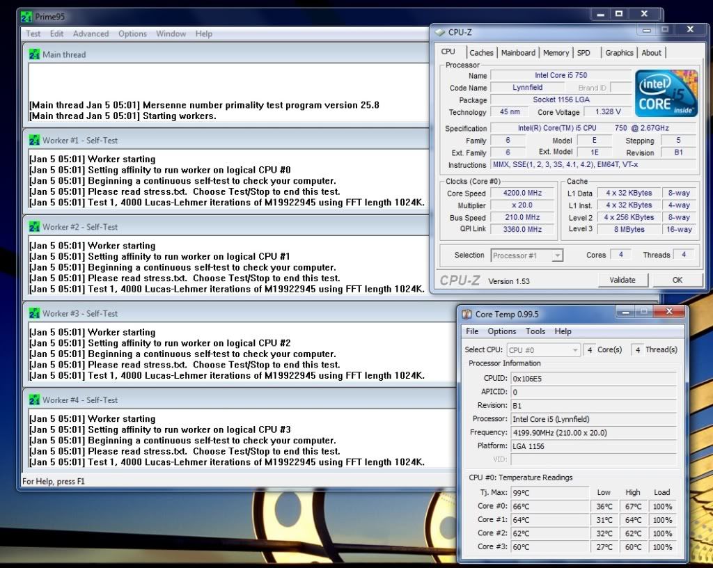
Running OCCT stress testing the system. (I am using Prime95, Intel Burn Test, OCCT and SuperPi).

Photobucket

4.2GHz, 30*C nominal @ Idle:

Photobucket

60-70*C @ 100% Prime95 (expect higher, around 80 in Intel Burn Test).

Photobucket

CPU Benchmark: 7257 (currently)

Photobucket

Geek specs:

Vcore1: 1.3v
Vcore2: 1.65v
FSB: 210MHz
CPU Multiplier: 20x
DRAM Multiplier: 6x

You can see the Vcore1 is quite low, yet stable. I want to see if I can juggle the FSB and the multipliers to give me a slightly faster RAM clock speed (currently 1260MHz). Interestingly I dropped the Vcore1 from 1.3850v to 1.3v to try and lower the temperature, and I took 1-2*C off the chip! This seems inconsequential, but it really isn't! Hence how I want to either bring the multiplier up, boost the Vcore1 voltage and test the temperatures, or really just get this puppy lean... Anyway, I think an 8 hour Prime95 test should be called upon before I do much more! I will post the results soon, so....

... tonight I will leave a stress test on, and maybe consider some sleep! Hot water bottle (I am such a nanny), some form of sitcom and hopefully a lie in (you can count on it!)

God bless!
Mike